
Current Electricity is an important topic in Physics that deals with the flow of electric charge through conductors. It explains concepts like electric current, potential difference, resistance, and Ohm’s law, which are essential to understand the working of electrical circuits in our daily life.
Current Electricity
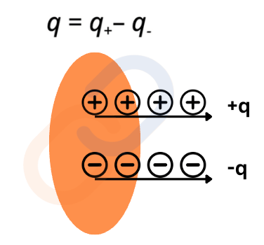
What is Electric Current?
- Electric current is the rate of flow of charge through a conductor.
- Imagine a cross-sectional area perpendicular to the direction of charge flow. The net charge (q = q+– q– )passing through this area per unit time is the current.
- Mathematical Definition of Current For a steady current,
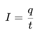
where:
- I = Electric current (in Amperes, A)
- q = Net charge passing through the cross-section (in Coulombs, C)
- t = Time interval (in seconds, s)
Instantaneous Current
If the current is not steady, we define an instantaneous current as:
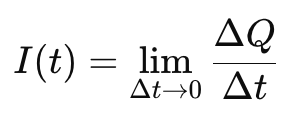
where ΔQ is the small charge flowing in time interval Δt.
SI Unit of Current: The Ampere
- The SI unit of current is the Ampere (A).
- 1 Ampere is defined as 1 Coulomb of charge flowing per second:1A=1 C/s
Magnitude of Current in Different Situations
- Household appliances: Few amperes
- Lightning strike: Thousands of amperes
- Current in human nerves: Microamperes (µA)
| Material Type | Free Electrons? | Conductivity | Examples | Uses |
| Conductors | Many | High | Copper, Silver, Gold | Wiring, circuits |
| Insulators | Very few | Very low | Rubber, Glass, Wood | Electrical insulation |
| Semiconductors | Moderate (variable) | Controlled | Silicon, Germanium | Microchips, transistors |
| Superconductors | Zero resistance at Tc | Perfect at low temp | Mercury, Niobium, YBCO | MRI, quantum computing |
Electric Currents in Conductors
What Makes a Material Conductive?
- For a material to conduct electricity, it must have free charge carriers.
- Types of Conductors:
- Metallic Conductors: Metals have a sea of free electrons that move freely. Conductivity decreases with temperature increase due to resistance.
- Pure Metals: Copper (Cu), Silver (Ag), Gold (Au), Aluminum (Al)
- Alloys: Brass (Cu + Zn), Bronze (Cu + Sn), Nichrome (Ni + Cr + Fe)
- Electrolytes: Solutions or molten salts where current flows due to moving ions instead of electrons.
- Liquid Electrolytes: Saltwater (NaCl solution), Acid solutions (HCl, H₂SO₄)
- Molten Salts: Molten NaCl, Molten KCl
- Superconductors: Below a certain critical temperature (T₀), resistance drops to zero. No energy loss, making them ideal for high-efficiency applications.
- Metals & Alloys: Mercury (Hg), Lead (Pb), Niobium (Nb)
- Ceramic Superconductors: YBCO (Yttrium Barium Copper Oxide)
- Semiconductor: Materials that behave as insulators at low temperatures but become conductors when energy (heat, light, voltage) is applied. Conductivity increases with temperature.
- Can be controlled by doping (adding small impurities).
- Examples:
- Intrinsic Semiconductors: Pure Silicon (Si), Germanium (Ge)
- Extrinsic Semiconductors (Doped): P-type (Boron-doped Si), N-type (Phosphorus-doped Si)
- Plasma & Gases: A superheated gas where atoms lose electrons, creating free ions and electrons that conduct electricity. Examples: Lightning ,Neon lights & Fluorescent bulbs
- Metallic Conductors: Metals have a sea of free electrons that move freely. Conductivity decreases with temperature increase due to resistance.
Effect of an Applied Electric Field
- In a neutral conductor, electrons move randomly due to thermal energy. There is no net current because the number of electrons moving in one direction equals those moving in the opposite direction.
- When a steady electric field is applied, electrons experience a force and drift in a particular direction. This ordered motion of electrons constitutes electric current.
F = -eE
- To maintain a continuous current, a device must continuously supply charge. This is done using cells, batteries, or power supplies. These devices create a steady electric field, ensuring a continuous flow of electrons.
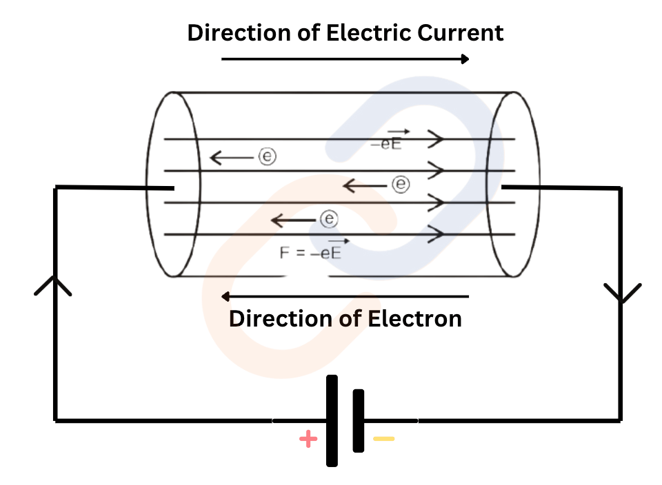
Direction of Current Flow
- Conventional Current Flow:
- Current flows from positive to negative in an external circuit.
- This was assumed historically before the discovery of electrons.
- Electron Flow (Real Flow of Charge):
- Electrons move from negative to positive inside the conductor.
- This is because electrons are negatively charged and move towards the positive terminal.
Note: In circuit diagrams, we follow the conventional current flow (positive to negative).
Electric Potential
Electric potential at a point in an electric field is the amount of work done in bringing a unit positive charge from infinity to that point without any acceleration.
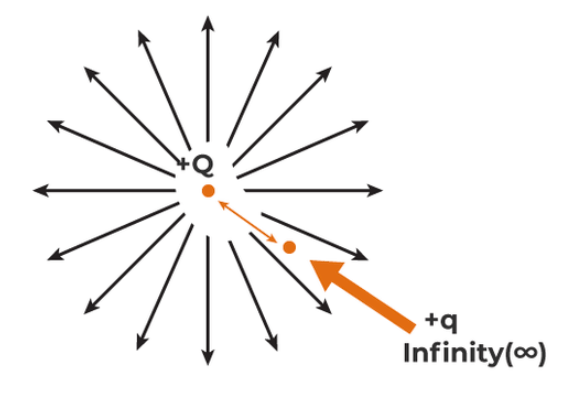
Formula:
V=W/q
Where:
- V = Electric potential (in volts)
- W = Work done (in joules)
- q = Charge (in coulombs)
Unit: Volt (V)
1 Volt = 1 Joule/Coulomb
Electric Potential Difference:
The potential difference between two points is the work done in moving a unit positive charge from one point to another.
Formula:
ΔV = VB−VA = W/q
Where:
- ΔV = Potential difference between point B and A
- W = Work done in moving the charge
- q = Charge
Unit: Volt (V)
Cells, EMF & Internal Resistance
A cell has two terminals: Positive (P) and Negative (N), dipped in a chemical solution (electrolyte) that produces electricity.
EMF (Electromotive Force)
- Total energy provided by a source (battery/cell) per unit charge
- It is the maximum potential difference when no current is drawn.
ε = V+ + V–
Internal Resistance (r)
- The electrolyte inside the cell resists the flow of current.
- This resistance is called internal resistance (r) of the cell.
- It reduces the voltage available to the external circuit.
Terminal Voltage
- The voltage available across the terminals when the circuit is ON
- Usually less than EMF due to internal resistance.
The voltage across the external resistor (R) becomes:
V = ε−Ir
Where:
- ε = EMF
- I = current
- r = internal resistance
Using Ohm’s law:
I= εR+r
Voltmeter and Ammeter
Voltmeter
- Measures potential difference across two points
- Connected in parallel
- Has high resistance
Ammeter
- Measures current
- Connected in series
- Has low resistance
AC vs. DC (Types of Current)
| Feature | Direct Current (DC) | Alternating Current (AC) |
| Definition | Current flows in one direction only. | Current changes direction periodically. |
| Source | Batteries, cells, solar panels | Power stations, generators, home electricity |
| Frequency | 0 Hz | 50 Hz (India), 60 Hz (USA) |
| Graph | Straight line (constant voltage) | Sinusoidal waveform (varying voltage) |
| Example | Used in mobile chargers, electronic devices | Used in household electricity, power grids |
Circuit Diagram:

Ohm’s Law
Ohm’s Law, discovered by G.S. Ohm in 1828, states:
The voltage across a conductor is directly proportional to the current flowing through it, provided the temperature remains constant.
Mathematical Expression:
V ∝ I
V = IR
where:
- V = Potential difference (volts, V)
- I = Current (amperes, A)
- R = Resistance (ohms, Ω)
R (resistance) is the proportionality constant, measured in ohms (Ω). It is the property of a material that opposes current flow.
- Resistance depends not only on the material of the conductor but also on its physical dimensions.
Dependence of Resistance on Material and Dimensions
The resistance R of a conductor is influenced by its length (l) and cross-sectional area (A):
- Effect of Length: Doubling the length of a conductor doubles its resistance.
R∝l (Increases with length)
- Effect of Cross-Sectional Area:
Doubling the cross-sectional area halves the resistance.
R ∝ 1A
(Decreases with cross-sectional area)
Combining the above two relationships:
R = ρ lA
where:
- ρ = Resistivity of the material (ohm-meter, Ω⋅m)
- l = Length of conductor (m)
- A = Cross-sectional area (m²)
Ohm’s Law : V=I×R
So: V =I ρ lA
Current Density (j)
j = IA
(Current per unit area, normal to the direction of current)
Units: A/m2
Using this in the voltage equation:
V = j ρ l
If a uniform electric field E is applied across the length l of the conductor, then:
V = E l
Combining this with the previous equation:
E l = j ρ l
⇒ E = j ρ
Ohm’s Law in Vector Form:
Since j and E have both magnitude and direction, we can write:

Where:
- 𝑗⃗ : Current density vector
- 𝐸⃗ : Electric field vector
- ρ : Resistivity of the material
- σ = 1/ρ : Conductivity of the material
j=σE
This is a vector form of Ohm’s law.
Limitations of Ohm’s Law
While Ohm’s Law is widely used, it does not apply in all situations:
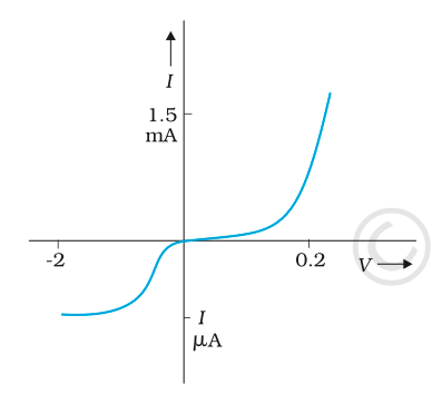
1. Non-Ohmic Materials
- Ohm’s law is valid only for ohmic conductors (like metals) where V∝I.
- It fails for non-ohmic materials like:Diodes, Transistors, Thermistors, Vacuum tubes
These materials do not show a linear V-I relationship.
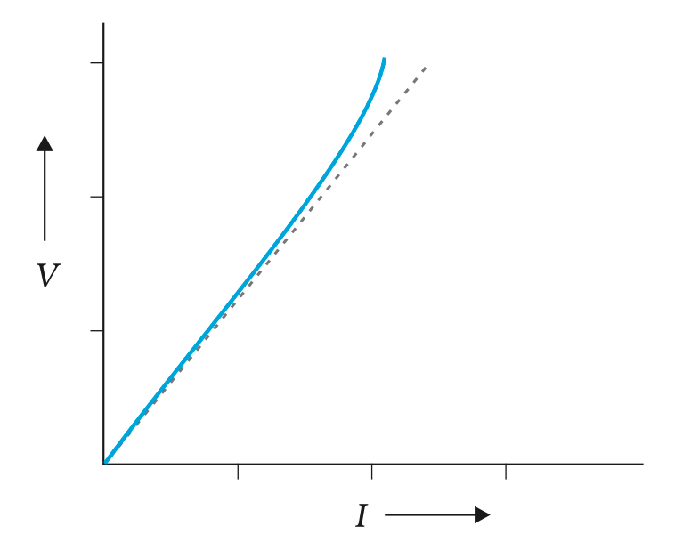
2. Temperature Dependence
- Ohm’s Law assumes resistance remains constant.
- But in reality, resistance changes with temperature, especially in:
- Filament of a bulb, Semiconductors
- So, if temperature varies, Ohm’s law may not hold true.
3. High Electric Fields
- Under very high electric fields, the material may:
- Break down (e.g., in gases)
- Show non-linear current response
- In such cases, Ohm’s law breaks down.
4. At Very Low Temperatures
- In superconductors, resistance becomes zero, and Ohm’s law becomes inapplicable because:
V=I×0=0(even if current flows)
5. AC (Alternating Current) Circuits
- Ohm’s law is simple for DC circuits, but in AC circuits, it must be modified to include:
- Reactance and impedance (due to inductors and capacitors)
Resistivity of Various Materials
| Material Type | Resistivity Range (Ω·m) | Examples |
| Conductors | 10-8 to 10-6(Low resistivity) | Copper, Silver, Aluminum (Metals) |
| Semiconductors | Between conductors and insulators(Moderate resistivity that decreases with temperature and is sensitive to impurities.) | Silicon, Germanium |
| Insulators | Up to 1018 times more than metals | Rubber, Plastic, Ceramic |
Types of Commercial Resistors
1. Wire-Bound Resistors
- Made by winding wires of manganin, constantan, nichrome.
2. Carbon Resistors
- Used in most electronic circuits.
- Compact, inexpensive.
- Resistance is shown using colour code (4 Bands).
Temperature Dependence of Resistivity
| Material Type | Effect of Temperature ↑ | Reason |
| Metals | Resistivity ↑ | τ ↓ (more collisions) |
| Semiconductors | Resistivity ↓ | n ↑ (more charge carriers) |
| Nichrome, Manganin, Constantan | Almost no change | Used for precision resistors |
- n = number of free electrons
- τ = average time between collisions
- In metals, n ≈ constant → ρ∝1/τ
- In semiconductors, n ↑ with temperature → resistivity ↓
Heating Effect of Electric Current
- A battery or cell provides electrical energy due to chemical reactions inside it.
- This energy causes electrons to flow, i.e., electric current through a circuit.
- Part of this energy may do useful work (like rotating a fan).
- The rest gets converted into heat, especially in resistive components (pure resistors).
- If the circuit contains only resistors, the entire energy supplied by the source gets converted into heat. This is called the Heating Effect of Electric Current.
Joule’s Law of Heating
When an electric current flows through a conductor, heat is produced due to the resistance offered by the conductor. The amount of heat produced (H) is directly proportional to:
- H∝I2 → More current, more heat.
- H∝R → More resistance, more heat.
- H∝t → More time, more heat.
Thus, when current I flows through a resistor R for time t, the heat produced is:
H = I2Rt
Where:
- H = Heat produced (in joules)
- I = Current (in amperes)
- R = Resistance (in ohms)
- t = Time (in seconds)
Alternatively, using Ohm’s Law V=IR, heat can also be written as:
H = VIt
Practical Applications of Heating Effect
1. Electric Appliances
- Many common devices work on this principle: Electric iron, Water heater, Oven, Toaster, Kettle
- These convert electrical energy into heat using high-resistance coils (like nichrome).
2. Electric Bulbs
- In filament bulbs, the filament (usually tungsten) gets very hot due to current.
- It emits light and heat.
- Tungsten is used because it has a very high melting point (3380°C).
- The bulb is filled with inert gases (like nitrogen or argon) to prevent oxidation and prolong filament life.
3. Electric Fuse
- A fuse is a safety device that protects circuits from excessive current.
- It contains a thin wire with a low melting point (like lead or tin).
- When current exceeds the safe limit, the wire melts, breaking the circuit and preventing damage.
- Fuses are rated: 1 A, 2 A, 5 A, 10 A, etc.
- Example: An electric iron uses 1 kW of power at 220 V.
Current = Power/Voltage=1000/220 ≈ 4.54 A
So, a 5 A fuse is suitable for safety.
ELECTRIC POWER
- Power is the rate of doing work or the rate of energy consumption.
- In electric circuits, it is the rate at which electrical energy is used or converted.
- Formula for Electric Power
P = VI
Using Ohm’s Law V = IR, we get:
P = I2R or
P = V2/R
Where:
- P = Power (in watts, W)
- V = Voltage (in volts, V)
- I = Current (in amperes, A)
- R = Resistance (in ohms, Ω)
Units of Electric Power
- Watt (W): Standard SI unit
1 watt = Power consumed when 1 ampere of current flows through a device at a potential difference of 1 volt
1 W = 1 V × 1 A = 1 VA
Electric Energy
- Electrical energy is the total power consumed over time.
- Energy consumed =Power×Time
- Unit: Watt-hour (Wh) or Kilowatt-hour (kWh)
1 kilowatt-hour (kWh):
1 kWh = 1000 W × 3600 s = 3.6×10⁶ J
This is the commercial unit of electric energy.
It is commonly referred to as 1 unit in electricity bills.
Example:
An electric geyser of 2 kW runs for 3 hours.
Energy consumed = Power × Time = 2 kW×3 h = 6 kWh = 6 units
Power Loss in Transmission Lines
- Power is transmitted from power stations to homes via long cables (which have resistance R).
- To deliver power P across a resistance R, current I = P/V.
- Power lost (wasted) in cables:
Ploss = I2R = P2R/V2
- Conclusion:

→ Increase voltage to decrease loss.
- Real-Life Implication: High-Voltage Transmission
- To reduce power loss, electric power is transmitted at very high voltages.
- At user end (homes/factories), a transformer is used to reduce voltage to a safe level.
- That’s why we see “DANGER: HIGH VOLTAGE” signs near power lines.
COMBINATION OF RESISTORS
1. SERIES COMBINATION
Resistors are in series when they are connected end-to-end, and the same current flows through each of them.

- Current I is the same in all resistors.
- Total voltage = sum of individual voltages.
V=V1+V2+V3+……
By Ohm’s law:
V= IR1 + IR2 + IR3 = I (R1 + R2 + R3) = IReq
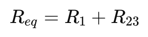
Formula for Equivalent Resistance (Req):
Req=R1+R2+R3+⋯+Rn
2. PARALLEL COMBINATION
Resistors are in parallel when both ends of the resistors are connected together, and the voltage across each resistor is the same.
- Voltage across each resistor is the same.
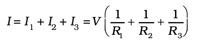
- Total current = sum of individual currents
I=I1+I2+I3+…
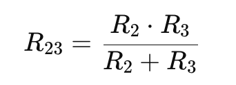
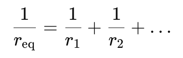
Formula for Equivalent Resistance (Req):
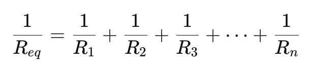
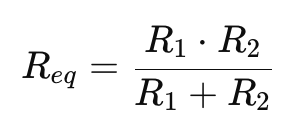
Or for two resistors:
Example: Mixed Circuit (Series + Parallel)
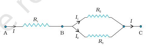
Total Current:
If voltage across the entire circuit is V, then:
| Feature | Series | Parallel |
| Current | Same through all resistors | Splits across resistors |
| Voltage | Splits across resistors | Same across all resistors |
| Equivalent Resistance | Sum of resistances | Less than the smallest resistance |
Cells in Series and Parallel
Cells in Series
Positive terminal of one cell is connected to the negative terminal of the next.
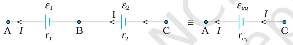
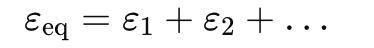
- Emf adds up:
- Internal resistance adds up:

- If one cell is reversed (opposite direction), its emf is subtracted.
Cells in Parallel
All positive terminals are connected together, and all negative terminals are connected together.
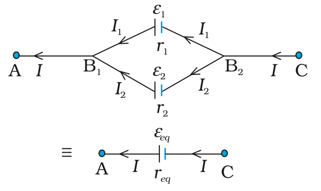
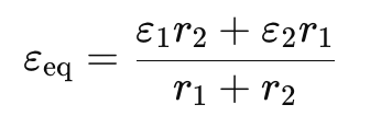
- Equivalent emf:
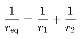
- Equivalent internal resistance:
General Rule for n Cells in Parallel
Emf:
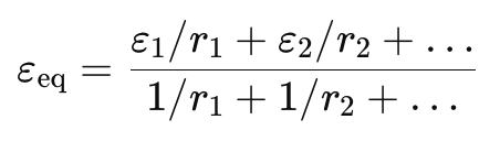
Resistance:
KIRCHHOFF’S RULES
In complex electric circuits, where resistors and cells are connected in various ways, we use Kirchhoff’s Rules to find the currents and potential differences in the circuit.
- Kirchhoff’s rules help analyze multi-loop and multi-branch circuits.
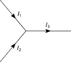
(a) Junction Rule (Conservation of Charge)
“The total current entering a junction = Total current leaving the junction”
- A junction is a point where 3 or more wires meet.
- Based on the law of conservation of electric charge—no charge gets lost or stored at the junction.
- Current is not “used up”; it splits or combines based on the circuit.
Mathematically:
∑Iin = ∑Iout
Example:
If I1 and I2 enter a junction, and I3 leaves, then
I1 + I2 = I3
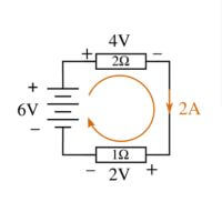
(b) Loop Rule (Conservation of Energy)
“The sum of the potential differences (voltage) around any closed loop is zero.”
- Follows from the fact that electric potential is a state function (like height), so returning to the same point means no net gain/loss in potential.
- Energy is conserved in a loop.
- The voltage gained (from batteries) is equal to the voltage lost (across resistors, etc).
Mathematically:
∑ΔV=0
WHEATSTONE BRIDGE
The Wheatstone Bridge is a special electric circuit used to find an unknown resistance accurately by using Kirchhoff’s Rules.
Structure of the Bridge
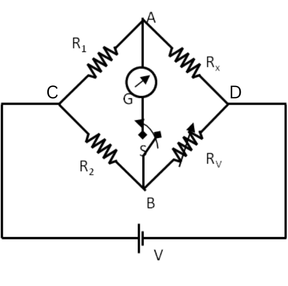
It has four resistors arranged in a diamond-like shape:
- R₁, R₂, RX, RV: placed in the four arms of the bridge.
- A battery is connected between points C and D (called the battery arm).
- A galvanometer (G) is connected between points A and B (called the galvanometer arm).
The bridge is said to be balanced when the galvanometer shows no deflection, i.e.,
Ig=0
Using Kirchhoff’s laws, we obtain the condition
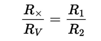
So, if R₁, R₂, RV are known and the galvanometer shows zero deflection, we can calculate RX.
The meter bridge is a real-world device that works on the principle of the Wheatstone Bridge to find unknown resistances using a 1-meter wire.
Difference between Static Electricity and Current Electricity
| Aspect | Static Electricity | Current Electricity |
| Definition | Refers to the build-up of electric charge on an object’s surface | Refers to the flow of electric charge through a conductor |
| Materials Involved | Insulating materials with high resistance | Conductive materials with low resistance |
| Causes | Contact-induced charge separation (Triboelectric effect)Charge-induced charge separation(electrostatic induction) | Occurs when electrons move from high to low potentialdriven by an external voltage source such as batteries, generators |
| Behavior of Charges | Charges remain stationary unless discharged | Charges continuously move through a circuit |
| Examples | Balloon rubbed against hair, clothing stuck together after drying, lightning | Electricity powering appliances Household appliances, electronics, industrial machinery |
| Uses | Air filters, dust-removal devices which take advantage of the charge differences between materials to remove airborne particles. | Electric currents create magnetic fields, which are used in motors, generators, inductors, and transformers.In ordinary conductors, they cause Joule heating, which creates light in incandescent light bulbs. |
| Magnetic Field | Does not induce magnetic field | Induces magnetic field |
| Measuring device | Gold leaf electroscope | ammeters |
