
Magnetism & Electro-Magnetism is an important topic in Physics that explains the behavior of magnets and the relationship between electricity and magnetism. It covers concepts such as magnetic fields, magnetic forces, and how electric currents can produce magnetism, forming the basis of many modern technologies like motors and generators.
Magnetism
What is Magnetism?
Magnetism is a force exerted by magnets when they attract or repel certain materials like iron, nickel, and cobalt.
- It is an invisible force.
- It acts at a distance.
- Magnetism is caused by the motion of electric charges (at the atomic level).
Magnetism is a universal phenomenon. From tiny atoms to huge galaxies, and even living beings, everything is surrounded by magnetic fields.
- Earth behaves like a magnet – with a magnetic field pointing from the geographic south to north.
- The word magnet comes from Magnesia, a place in Greece where magnetic stones were discovered around 600 BC.
How is Magnetism Related to Electricity?
In the 19th century, scientists like Oersted, Ampere, Biot, and Savart discovered that:
Electric currents (moving charges) produce magnetic fields.
So, electricity and magnetism are deeply connected — this connection forms the basis of electromagnetism.
Properties of Magnets:
- Poles: Every magnet has two poles — North (N) and South (S).
- Law of Magnetism:Like poles repel, and unlike poles attract.
- North ↔ North or South ↔ South: ❌ Repel
- North ↔ South: ✅ Attract
- Poles Always Exist in Pairs: You can’t isolate north or south pole.
- Magnetic monopoles do not exist.
- Directional Property: A freely suspended magnet always aligns in the North-South direction.
- Attraction is Stronger at Poles: Magnetic strength is maximum at the ends.
- Magnetic Induction: Magnetic materials can be magnetized temporarily when placed near a magnet.
- Magnets can be made from iron and its alloys.
Natural and Artificial Magnets
Natural Magnets:
- Found in nature.
- Example: Lodestone (a naturally magnetized mineral – magnetite).
- Weak magnetic strength.
- Historically used in navigation (ancient compasses).
Artificial Magnets:
- Made by magnetizing magnetic materials.
- Stronger and can be shaped.
- Types:
- Bar magnet
- Horseshoe magnet
- Disc magnet
- Electromagnet (explained later)
Magnetic Field and Field Lines
What is a Magnetic Field?
The region around a magnet where magnetic force can be felt is called the magnetic field.
Denoted by B, unit is Tesla (T).
Magnetic Field Lines:
Imaginary lines that show the direction of magnetic force.
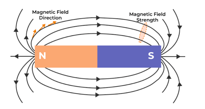
Magnetic Field Lines – Features:
- Closed loops:
- Magnetic field lines go from North to South outside the magnet, and South to North inside.
- They never start or end — they always form closed loops.
- This is different from electric field lines, which go from positive to negative.
- Direction of field:
- At any point, the tangent to a field line shows the direction of the magnetic field at that point.
- Strength of field:
- Where the field lines are closer together, the magnetic field is stronger.
- Where they are spread apart, the field is weaker.
- Field lines never cross:
- If they did, the direction of the magnetic field would be ambiguous, which is not possible.
How to Visualise Magnetic Fields?
You can map magnetic field lines by:
- Sprinkling iron filings over a glass plate placed on a magnet.
- Using a small compass and moving it around the magnet:
- The compass needle aligns itself with the direction of the field.
Earth’s Magnetism
1. Nature of Earth’s Magnetic Field
- The Earth acts like a giant magnet with a magnetic field of strength ≈ 10⁻⁵ T.
- Earlier believed to be due to a giant bar magnet deep inside the Earth — but this is not true.
- The field is now explained by the dynamo effect:
➤ Convection currents in the Earth’s molten iron–nickel outer core generate electric currents → produce magnetic field.
Note →
- The Moon has no significant magnetic field (no molten core).
- Jupiter (fastest rotating planet) has the strongest magnetic field.
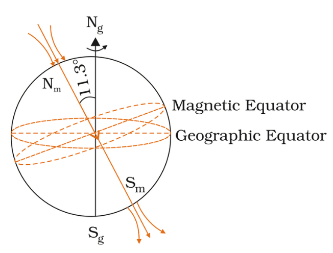
Earth as a Magnetic Dipole
- The Earth’s magnetic field resembles that of a bar magnet (dipole) placed at the center of the Earth.
- The axis of the magnetic dipole is tilted by 11.3° from the Earth’s rotation axis.
- Magnetic Poles:
- North Magnetic Pole: ~79.74° N, 71.8° W (near northern Canada).
- South Magnetic Pole: ~79.74° S, 108.22° E (in Antarctica).
- Note: Unlike in the case of a bar magnet, the field lines go into the earth at the north magnetic pole (Nm) and come out from the south magnetic pole (Sm).
North Magnetic Pole = behaves like south pole of a bar magnet,
South Magnetic Pole = behaves like north pole.
Magnetic Declination (D):
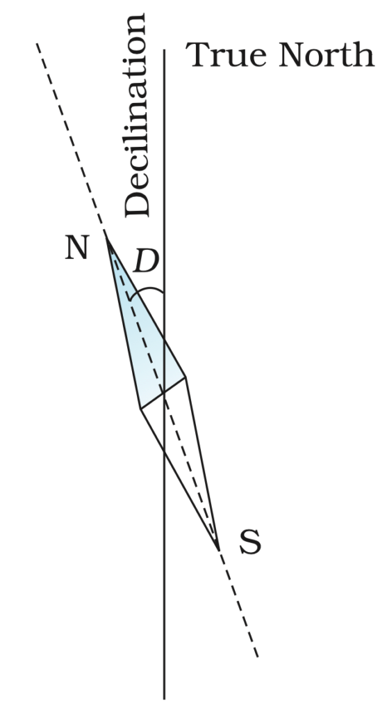
- The angle between true geographic north and magnetic north. {angle between the magnetic meridian and the geographic meridian at a place}
- Navigators must account for this to accurately read a compass.
- Varies by location:
- Delhi: 0°41′ E
- Mumbai: 0°58′ W
Magnetic Dip or Inclination (I):
- The angle between the horizontal and the magnetic field line at a place is called inclination or dip.
- At magnetic equator → dip is 0°
- At magnetic poles → dip is 90°
Compass at the Poles
- A regular compass works on the horizontal component of the magnetic field.
- At the magnetic poles, this component is nearly zero, so the compass fails.
- A dip needle is used to measure the angle of dip in such cases.
Variations in Earth’s Magnetic Field
➤ With Position:
- Solar wind (charged particles from the Sun) disturbs the field, especially near poles → causes phenomena like auroras.
➤ With Time:
- Short-term changes: e.g., declination at London changed by 3.5° in 240 years (1580–1820).
- Long-term changes:
- Magnetic poles drift over centuries.
- Reversal of polarity over millions of years (proved through studies of basalt rocks with fossil magnetism).
Magnetic Dipole:
- A system with two equal and opposite magnetic poles separated by a distance.
- Example: Bar magnet
Magnetic Dipole Moment (M or m)
A vector quantity representing the strength and orientation of a magnetic dipole.
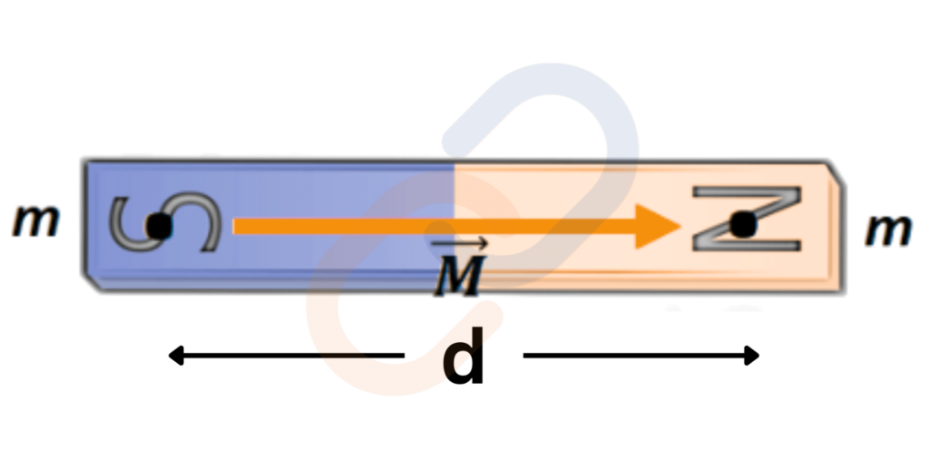
Formula:
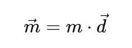
Where:
- m = magnetic pole strength
- d = distance vector from south to north pole
Unit: Ampere-meter² (A·m²) or Joules per Tesla (J/T)
Direction: From South to North inside the magnet
Torque on a Magnetic Dipole in Uniform Magnetic Field
When a magnetic dipole is placed in a magnetic field, it experiences a torque:
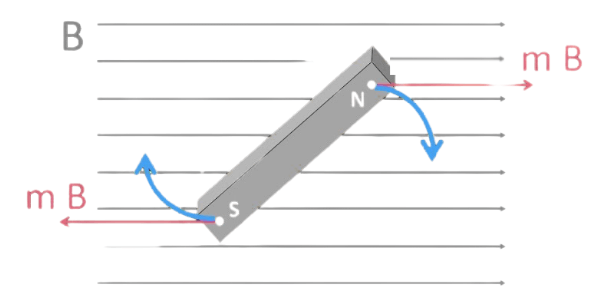
Formula:
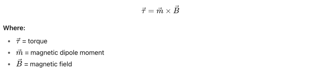
Tends to align the dipole with the field (just like compass needle aligns with Earth’s field)
Potential Energy of a Magnetic Dipole
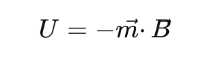
Minimum energy when dipole is aligned with B (stable equilibrium)
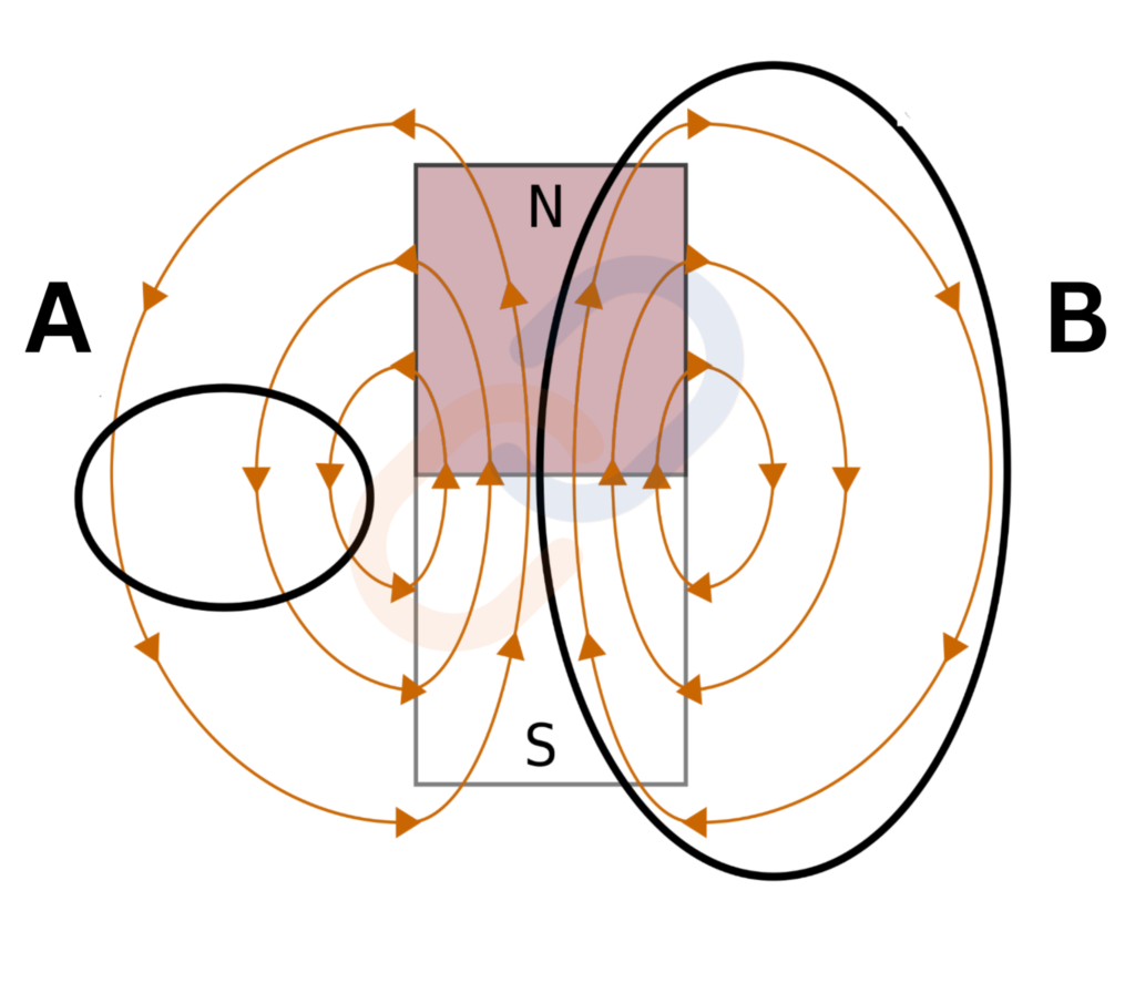
Gauss’s Law for Magnetism
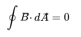
- The net magnetic flux through a closed surface is zero.
- Reason: Magnetic monopoles do not exist — magnetic poles always come in pairs (North and South).
- The difference between Gauss’s law of magnetism and that for electrostatics is a reflection of the fact that isolated magnetic poles (also called monopoles) are not known to exist.
Permeability (μ)
Permeability is a measure of how easily a material can support the formation of a magnetic field within itself.
- It tells us how well magnetic field lines can pass through a material.
- Symbol: μ
- SI Unit: Henry per meter (H/m)
Permeability of Free Space (μ₀)
Also called the magnetic constant, it is the permeability of vacuum (free space).
μ0 = 4π×10-7 H/m
Magnetisation (M)
Magnetisation is the magnetic moment per unit volume of a material.
Formula:
M= mnet / V
where:
- M = Magnetisation (A/m)
- mnet = Net magnetic moment of the material
- V = Volume of the material
Explanation:
- When a material is placed in a magnetic field, its atomic dipoles try to align with the field.
- The extent to which the material gets magnetised is measured by M.
- It depends on how easily the magnetic dipoles align.
Magnetic Intensity (H)
(Also called Magnetic Field Intensity or Magnetising Field)
Definition: It is the measure of the external magnetic field (like current in the solenoid)applied to a material to magnetise it.
Formula:

Or
Where:
- H = Magnetic intensity (A/m)
- B = Magnetic field (Tesla)
- μ = Permeability of the material
- μ0 = Permeability of free space
- M = Magnetisation
Explanation:
- H tells us how strong the applied field is, regardless of the material.
- It is independent of the medium’s response.
- It’s what causes the material to become magnetised.
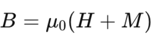
Relation between B, H, and M
Magnetic field (B) inside a material is affected by both:
- the applied magnetic field (H), and
- the material’s response (magnetisation M)
B = μ0 (H+M)
Or, using permeability μ:
B = μH
Magnetic Susceptibility (χ)
- Magnetic Susceptibility measures how easily a material can be magnetised in response to an external magnetic field.
- It shows the degree of magnetisation (M) of a material when exposed to a magnetising field (H).
Formula:
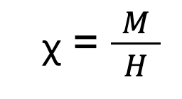
Where:
- χ = Magnetic susceptibility (dimensionless)
- M = Magnetisation (A/m)
- H = Magnetic field intensity (A/m)
Key Points:
- It is a dimensionless quantity (no units).
- Indicates how “magnetically responsive” a material is.
- Higher χ means the material gets magnetised more easily.
Types of Materials Based on χ:
| Type of Material | Susceptibility (χ) | Behavior in Magnetic Field |
| Diamagnetic | χ < 0 | Weakly repelled |
| Paramagnetic | χ > 0 (small) | Weakly attracted |
| Ferromagnetic | χ ≫ 1 (very large) | Strongly attracted |
Relation Between μr and χ:
B = μ0 (H+M)
χ = MH
So ,
B = μ0 (1+ χ) H
B = μ0 μr H
B = μ H
Where μr = 1 + χ , is a dimensionless quantity called the relative magnetic permeability of the substance.
Relative Permeability (μᵣ)
Relative permeability is the ratio of the permeability of a material to that of free space:
μr = μ / μ0
So,
μ = μ0 μr = μ0 (1+ χ)
- μr > 1: for magnetic materials (ferromagnetic)
- μr < 1: for diamagnetic materials
μr ≈ 1: for non-magnetic materials (like vacuum or air)
Magnetic Properties of Materials
What is Magnetism in Materials?
Magnetism arises due to moving charges—primarily the motion of electrons around the nucleus and their spin. In most atoms, paired electrons cancel each other’s magnetic effects. But in atoms with unpaired electrons, there’s a net magnetic moment, which interacts with an external magnetic field.
When materials are placed in a magnetic field, they respond differently depending on their electronic structure and atomic alignment.
Materials can be classified based on their magnetic behavior into Diamagnetic, Paramagnetic, and Ferromagnetic Substances. This classification is based on magnetic susceptibility (χ) and relative permeability (μr):
| Type | Susceptibility (χ) | Relative Permeability (μr) | Permeability (μ) |
| Diamagnetic | –1 ≤ χ < 0 | 0 ≤ μr < 1 | μ < μ₀ |
| Paramagnetic | 0 < χ < ε (small +ve) | 1 < μr < 1 + ε | μ > μ₀ |
| Ferromagnetic | χ >> 1 | μr >> 1 | μ >> μ₀ |
Diamagnetism
Definition:
- Diamagnetic substances are repelled by magnetic fields.
- They move from the stronger to the weaker part of a magnetic field.
- Diamagnetism arises due to Lenz’s Law and is fundamentally a quantum mechanical effect:
- When an external magnetic field is applied to a material, the orbital motion of electrons in atoms changes in such a way that it creates an induced magnetic field in the opposite direction.
- This induced magnetic field opposes the applied magnetic field — making the material weakly repelled by the magnet.
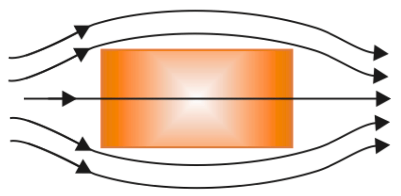
Diamagnetic substance.
Explanation:
- Electrons orbiting around nuclei have orbital angular momentum → act like small current loops → have orbital magnetic moments.
- Only paired electrons are present. Each pair of electrons has opposite spins, so their magnetic moments cancel each other out. This is why diamagnetic substances do not have a permanent magnetic moment.
- When an external magnetic field is applied, they show a weak repulsion due to the induced magnetic moment (as per Lenz’s Law).
- According to Lenz’s Law, when a magnetic field is applied, these loops adjust to oppose the change in magnetic flux:
- Electrons opposing the field speed up.
- Electrons aligned with the field slow down.
- This leads to a small magnetic moment opposite to the applied field.
- Hence, the material is repelled by the magnetic field.
Effect on Magnetic Field:
- Reduces magnetic field inside material.
- Weak effect (~1 part in 10⁵).
- Field lines are slightly repelled .
Examples:
- Bismuth, copper, lead, silicon, nitrogen (at STP), water, sodium chloride.
Note:
- Diamagnetism is present in all materials, but usually overshadowed by stronger effects like paramagnetism or ferromagnetism.
Special Case: Superconductors
- At very low temperatures, superconductors exhibit:
- Perfect conductivity
- Perfect diamagnetism: χ = –1, μr = 0
- Field lines are completely expelled (Meissner effect).
- They repel magnets and are themselves repelled.
- Used in magnetically levitated (maglev) trains.
Paramagnetism
Definition:
- Paramagnetic materials are weakly attracted to magnetic fields.
- They move from weaker to stronger regions of magnetic field.
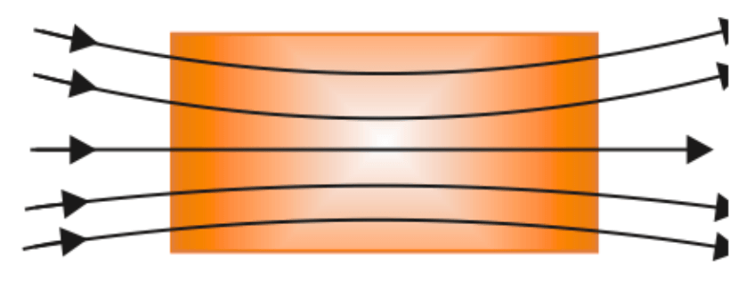
paramagnetic substance.
Explanation:
- At least one unpaired electron is present.
- Unpaired electrons have a net magnetic moment (spin not cancelled).
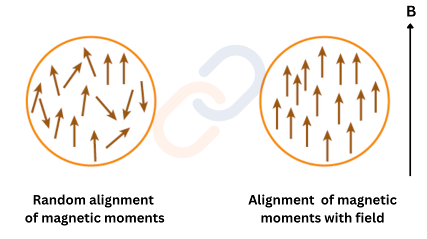
- Due to thermal motion, these moments are randomly oriented → net magnetisation = 0.
- The magnetic effect increases at low temperatures (more alignment).
- When placed in an external magnetic field:
- Dipoles tend to align with the field.
- Net magnetisation appears in the direction of the field.
Effect on Magnetic Field:
- Magnetic field inside the material is enhanced slightly .
- Weak effect (~1 part in 10⁵).
Examples:
- Aluminium, sodium, calcium, oxygen (at STP), copper chloride.
Dependence on Temperature:
Curie’s Law:
- Magnetisation (M) of a paramagnetic material is directly proportional to the applied magnetic field (B₀) and inversely proportional to the absolute temperature (T):
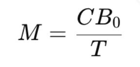
- Magnetic susceptibility (χ) also follows:
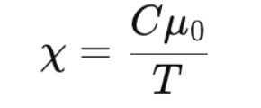
- C is Curie’s constant, a material-specific value.
- μ₀ is the permeability of free space.
Important Notes:
- As temperature decreases or field strength increases, magnetisation increases.
- Saturation (Mₛ): Occurs when all dipoles align with the magnetic field. Beyond this, Curie’s Law doesn’t hold.
Ferromagnetism
Definition:
- Ferromagnetic materials are strongly attracted to magnetic fields.
- Move from weak to strong magnetic field regions.
Explanation:
- Unpaired Electrons: Ferromagnetic materials have multiple unpaired electrons, which contribute to a net magnetic moment.
- Exchange Interaction (Quantum Effect): A quantum mechanical force called exchange interaction causes the magnetic moments of neighboring atoms to align in the same direction — even without an external field.
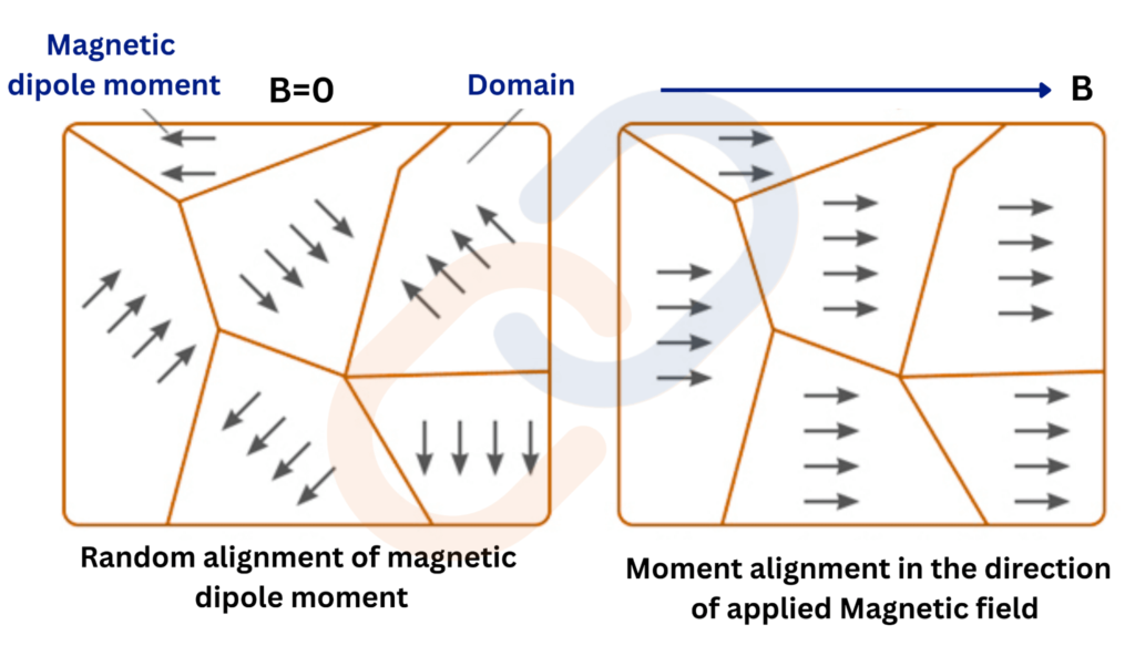
- Formation of Domains: At the microscopic level, these materials are divided into tiny regions called magnetic domains. Within each domain, magnetic moments are aligned.
- Domains are macroscopic regions (~1 mm) containing ~10¹¹ atoms.
- Initially, domain directions are random → no net magnetisation
- When a magnetic field is applied, domains align more strongly → material becomes magnetized.
- Retentivity (Hysteresis): Even after the external field is removed, the domains stay aligned — leading to permanent magnetism.
- This effect can be observed using microscope and powder suspension.
Effect of Removing Field:
- In some materials, magnetisation persists:
- These are called hard magnetic materials (e.g., Alnico, lodestone).
- Used for permanent magnets, compasses, etc.
- In others, magnetisation disappears:
- These are soft magnetic materials (e.g., soft iron).
- Used in electromagnets, transformers, etc.
➤ Examples:
- Iron, cobalt, nickel, gadolinium.
Relative Permeability:
- Can be greater than 1000 (very strong effect).
Effect of Temperature:
- As temperature increases, domain structure breaks down.
- At a critical temperature called the Curie Temperature (Tₛ), ferromagnetic material becomes paramagnetic.
- This change is gradual and resembles a phase transition.
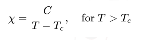
Above Curie Temperature:
- The susceptibility follows a modified Curie’s law:
Hysteresis
In magnetism, hysteresis refers to the lag between the magnetizing force (H) applied to a magnetic material and the resulting magnetic field (B or M) in the material.
Magnetic Hysteresis:
When you magnetize a ferromagnetic material like iron, and then reduce the magnetic field:
- The material does not immediately return to zero magnetism.
- Some magnetism remains — called residual magnetism or retentivity.
- You must apply a reverse field to demagnetize it completely — this is called coercivity.
Hysteresis Loop (B-H Curve):
- It’s a graph between Magnetic Field Strength (H) and Magnetic Flux Density (B).
- It shows how a material gets magnetized and demagnetized.
- Not Linear: The relation between magnetic field (B) and magnetic intensity (H) is not linear and depends on the magnetic history of the material.
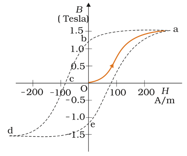
Hysteresis Loop
- Oa: Initial magnetisation; B increases and saturates.
- ab: H reduced to 0; B remains ≠ 0 → called Retentivity
- bc: H reversed; B becomes zero at Coercivity
- cd: Reverse saturation achieved.
- de → ea: Cycle continues; curve does not retrace, showing lag (hysteresis).
Loop Area: Energy loss per cycle (as heat)
Hysteresis = Lag of B behind H due to domain behavior.
Why is Hysteresis Important?
- The area of the loop = energy lost as heat during magnetization and demagnetization.
- This is called hysteresis loss.
- It’s important in designing transformer cores, motors, etc.
| Material | Hysteresis Loop | Uses |
| Soft iron | Small loop (low loss) | Transformers |
| Steel | Large loop (high retentivity) | Permanent magnets |
Permanent Magnets
- Definition: Substances that retain ferromagnetism at room temperature for a long time.
- Methods to Make:
- Hammering an iron rod in north-south direction.
- Stroking a steel rod with a bar magnet repeatedly.
- Best Method: Place a ferromagnetic rod in a solenoid and pass current.
- Material Requirements:
- High Retentivity → Strong magnet.
- High Coercivity → Resists demagnetisation.
- High Permeability.
- Examples: Steel, Alnico, Cobalt steel, Ticonal.
Electromagnets
An electromagnet is a temporary magnet created by passing current through a coil wound around a soft iron core.
Features:
- Magnetic field is controllable
- Becomes stronger with more turns, more current, or better core
- Loses magnetism when current stops
Properties Required:
- High Permeability → Strong magnetic field.
- Low Retentivity → Easily switchable off.
Applications:
- Electric bells, loudspeakers, telephone diaphragms.
- Cranes for lifting heavy iron and steel parts.
Magnetic Materials in AC Applications
- Uses: Transformers, telephone diaphragms.
- Material Requirements:
- Narrow Hysteresis Loop → Less energy loss.
- High Resistivity → Reduce eddy current losses.
Magnetic Effects of Electric Current
Oersted’s Experiment
Discovery of Magnetic Effect of Current
Background:
Before 1820, electricity and magnetism were seen as separate phenomena.
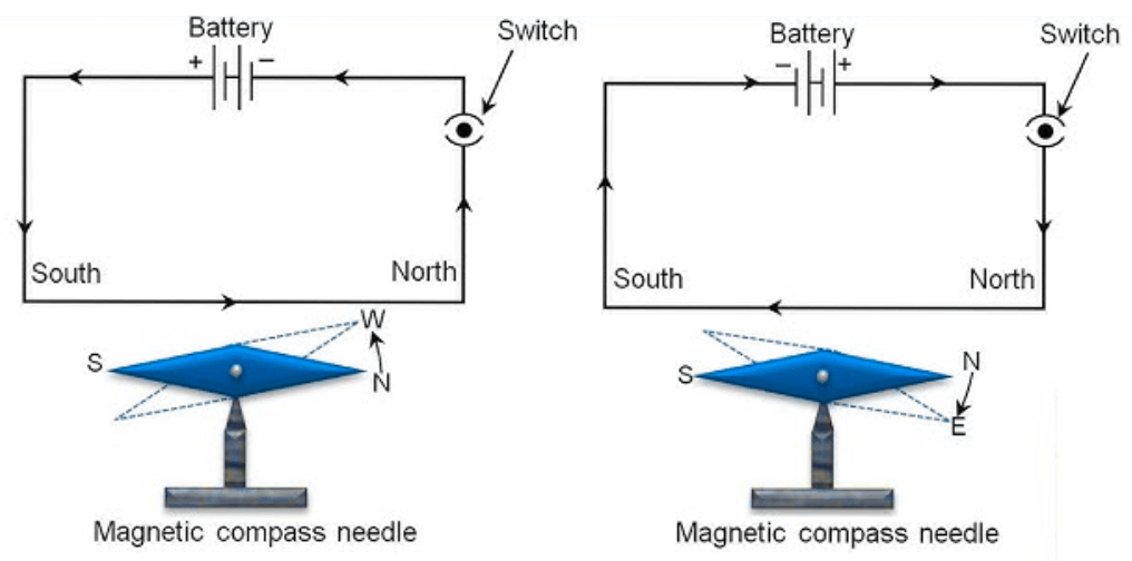
Hans Christian Oersted’s Observation:
- When a current-carrying wire is placed near a compass needle, the needle deflects.
- The deflection changes direction when the current is reversed.
This experiment was the first evidence of the link between electricity and magnetism.
“Electric current produces a magnetic field” → Foundation of electromagnetism
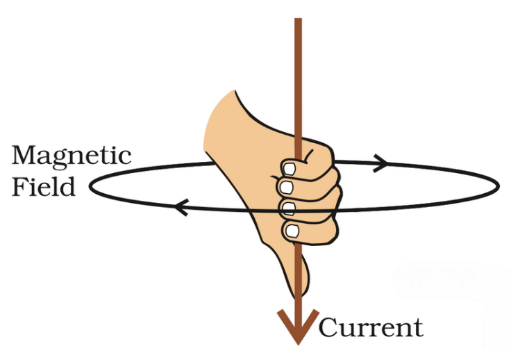
Right-Hand Thumb Rule (Direction of Field)
- Hold the straight current-carrying conductor in your right hand with the thumb pointing in the direction of current. Then, the fingers curl around in the direction of magnetic field lines.
- This rule helps predict the direction of magnetic field around: Straight wires, Circular loops, Solenoids
Magnetic Field due to Current
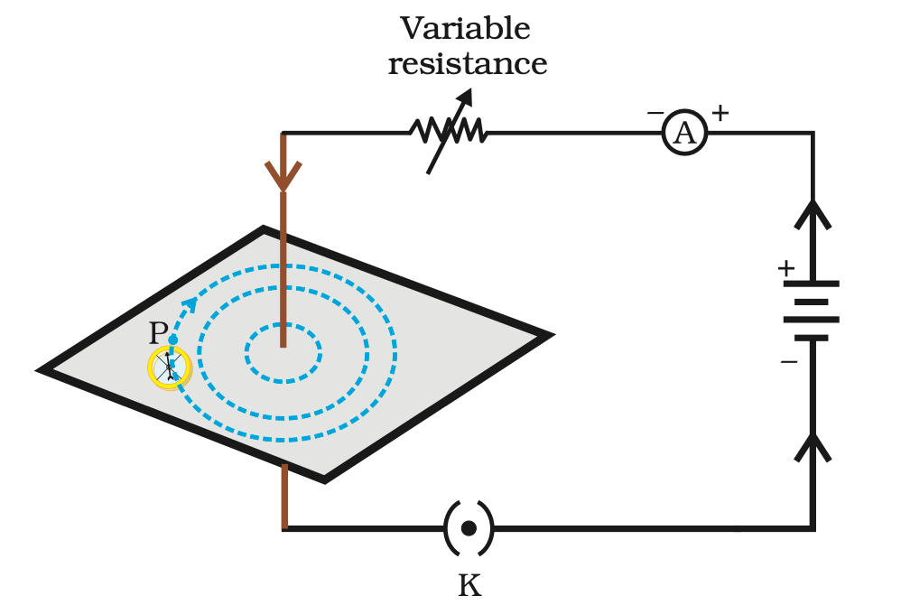
1. Straight Conductor (Wire)
- Pattern: Magnetic field lines form concentric circles around the wire.
- Effect of Current:
⬆️ Current → ⬆️ Magnetic field strength.
⬇️ Current → ⬇️ Magnetic field strength. - Effect of Distance:
⬆️ Distance from wire → ⬇️ Magnetic field strength. - Observation: Compass needle deflects more when closer and less when farther.
2. Circular Loop
- Pattern: Magnetic field lines are circular near the wire, but become nearly straight at the center.
- Field Direction: Same direction at the center due to all loop segments (use right-hand rule).
- Factors Increasing Magnetic Field Strength:
- Increasing current (I)
- Decreasing radius of the loop
- Increasing number of turns
- More turns (n) → Stronger field
- Field at the center = n times that of a single loop
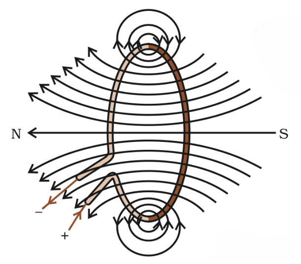
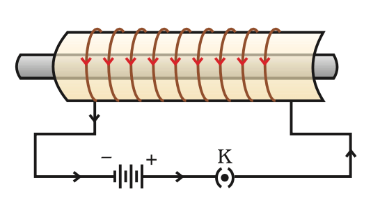
3. Solenoid
- Definition: A coil of many circular turns of insulated wire in a cylindrical shape.
- Field Pattern: Similar to a bar magnet:
- Inside: Field lines are parallel and straight → Uniform magnetic field.
- Ends: Behave like north and south poles.
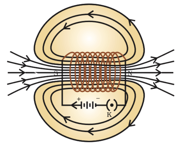
- Use: Strong magnetic field can magnetize soft iron, creating an electromagnet.
Force on a Current-Carrying Conductor in a Magnetic Field
When a current-carrying conductor is placed in a magnetic field, it experiences a mechanical force.
This is due to the interaction between the moving charges (electrons) in the conductor and the external magnetic field.
This phenomenon forms the principle of electric motors, speakers, and many industrial devices.
Andre Marie Ampere stated that:If a current-carrying conductor can exert a force on a magnet, then the magnet also exerts an equal and opposite force on the conductor (Newton’s third law).
Observation
When a current-carrying rod (like aluminium) is placed between the poles of a magnet:
- The rod moves, showing that a force is acting on it.
- If we reverse the direction of current, the direction of force also reverses.
- Similarly, if we change the magnetic field’s direction, the force again reverses.
Conclusion: The direction of the force depends on both:
- Direction of current
- Direction of magnetic field
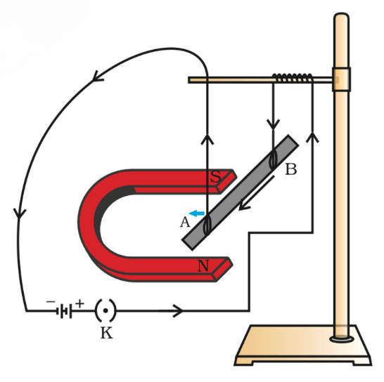
Direction of Force: Fleming’s Left-Hand Rule
Stretch out your left hand:
- Forefinger → Direction of magnetic field (N to S)
- Middle finger → Direction of current
- Thumb → Direction of force/motion of the conductor
These three directions are mutually perpendicular (90° to each other).

Reason → Lorentz Force:
Electric current is moving charges (electrons). When these charges move in a magnetic field, they experience a force called the Lorentz Force.
For a single charge, the magnetic force is:
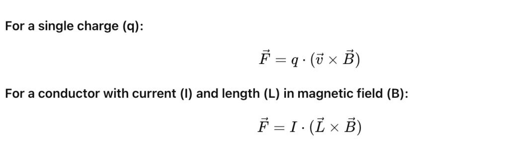
- F = Magnetic force (vector)
- I = Current in the wire (Ampere)
- L = Vector length of conductor (magnitude is length, direction is current direction)
- B = Magnetic field (Tesla)
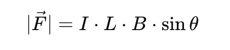
- θ = angle between current direction and magnetic field direction
REAL-WORLD APPLICATIONS:
| Application | Description |
| Electric Motors | Rotating coils feel magnetic force and spin. |
| Loudspeakers | Vibrate due to force on a coil in a magnetic field. |
| Galvanometers | Needle deflects due to magnetic force on coil. |
Practical Application: Electric Motor
What is an Electric Motor?
- An electric motor is a device that converts electrical energy into mechanical energy.
- It works on the principle that a current-carrying conductor placed in a magnetic field experiences a force.
Basic Principle:
- The motor is based on Lorentz Force and Fleming’s Left-Hand Rule.
When a current flows through a wire inside a magnetic field:
- One side of the wire is pushed up
- The other side is pushed down
→ This creates a rotational motion
Main Components:
| Part | Function |
| Armature (coil) | A rectangular loop of wire where current flows |
| Magnets (field) | Provide a uniform magnetic field (usually permanent or electromagnets) |
| Split-ring Commutator | Reverses current direction every half turn to keep the coil rotating |
| Brushes | Conduct electricity from the battery to the rotating coil |
| Power source (battery) | Supplies current to the coil |
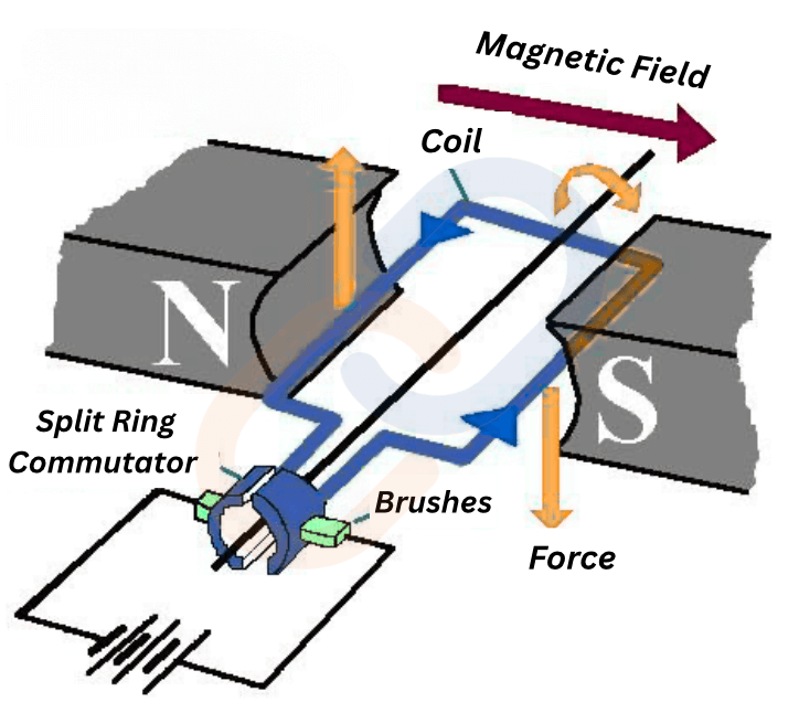
How It Works – Step-by-Step:
- Current flows through the coil.
- Magnetic field interacts with the current → force acts on the coil.
- One side of the coil is pushed up, the other down → rotation begins.
- The split-ring commutator reverses current direction after each half turn.
- Rotation continues in the same direction
Uses of Electric Motors:
- Fans and mixers, Washing machines, Electric vehicles, Trains, Elevators and escalators
Magnetism in Medicine
- An electric current always produces a magnetic field.
- In the human body, weak electric currents flow through nerve cells. These ion currents produce very weak magnetic fields, about one-billionth the strength of Earth’s magnetic field.
- For example, when we touch something, nerve impulses are sent to muscles. These impulses generate temporary magnetic fields.
Key Organs Producing Magnetic Fields: Heart , Brain
- These organs produce measurable magnetic fields.
- The magnetic fields inside the body form the basis for creating images of internal organs.
Medical Use: MRI (Magnetic Resonance Imaging):
- MRI uses the body’s magnetic fields to create detailed images of internal organs.
- These images are used for diagnosing diseases and medical conditions.
Electromagnetic Induction
We’ve already seen how electricity can produce magnetism — a current-carrying wire creates a magnetic field. But can the reverse also happen?
What if magnetism could produce electricity?
The answer is YES — and this groundbreaking idea is known as electromagnetic induction. It is the principle behind power generation, discovered by Michael Faraday in 1831.
What is Electromagnetic Induction?
Electromagnetic induction is the process of producing an electric current or electromotive force (EMF) in a conductor when it is exposed to a changing magnetic field.
Concept:
If you move a magnet near a coil or coil near a magnet, a current is induced in the coil. This happens without any battery.
Faraday’s Experiments (Discovery)
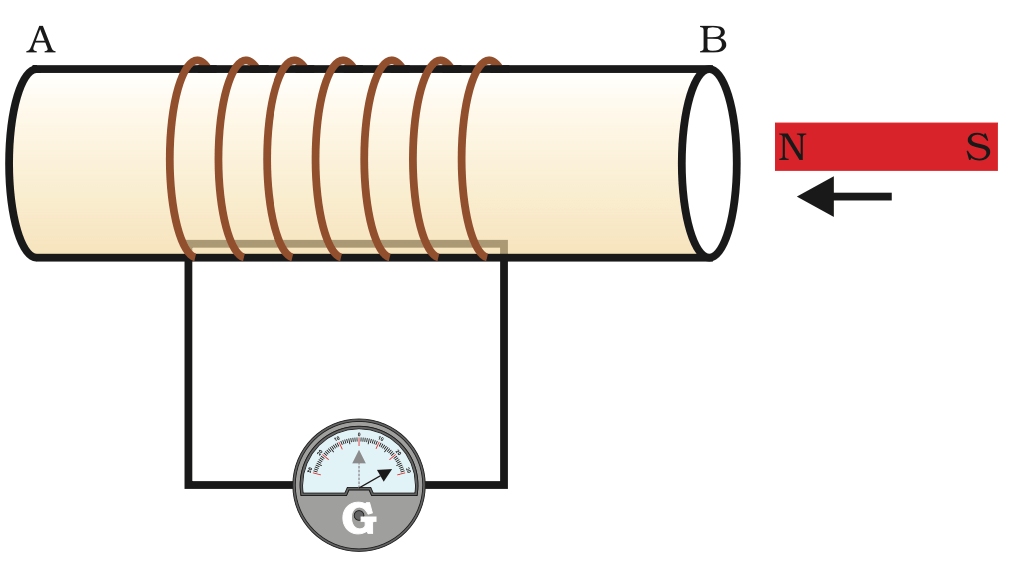
Michael Faraday performed a series of experiments:
- Experiment 1: A coil connected to a galvanometer. When a magnet is moved towards/away from the coil, the needle deflects.
- Experiment 2: If the magnet is held stationary → no deflection.
- Experiment 3: If the coil is moved and the magnet is fixed → deflection still occurs.
Conclusion: Relative motion between magnet and coil produces current.
Faraday’s Laws of Electromagnetic Induction
First Law:
- Whenever the magnetic flux linked with a coil changes, an EMF is induced in the coil. If the coil is part of a closed circuit, a current also flows.
- Change in magnetic field⇒Induced EMFChange in magnetic field⇒Induced EMF
Second Law:
- The magnitude of the induced EMF is directly proportional to the rate of change of magnetic flux.
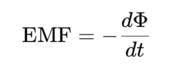
Where:
- ϕ = magnetic flux = B⋅A⋅cos(θ)
- The negative sign comes from Lenz’s Law. It shows that the induced emf opposes the change in magnetic flux (Φ).
Lenz’s Law: Conservation in Action
- The direction of the induced current is such that it opposes the cause that produced it.
Why the minus sign?⛔
- It ensures that energy is conserved. If the induced current aided the magnetic change, it would violate conservation of energy.
- E.g., when a magnet is pushed into a coil, the coil generates a repelling magnetic field to resist the push.
What is Lenz’s Law?
Lenz’s Law tells us the direction of the induced current when magnetic flux changes in a coil.
Statement:
The direction of induced current is such that it opposes the change in magnetic flux that caused it.
Named after Heinrich Lenz (1834).
Why the minus sign?⛔
It ensures that energy is conserved. If the induced current aided the magnetic change, it would violate conservation of energy.
E.g., when a magnet is pushed into a coil, the coil generates a repelling magnetic field to resist the push.
How It Works – An Example
Imagine a bar magnet approaching a coil:
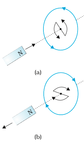
Case 1: North-pole moves towards the coil
- Magnetic flux increases.
- Coil produces a current that opposes this increase.
- So it behaves like a North-pole, repelling the approaching magnet.
- Current flows in a counter-clockwise direction (seen from magnet side).
Case 2: North-pole moves away from the coil
- Magnetic flux decreases.
- Coil produces current to oppose the decrease.
- It behaves like a South-pole, attracting the receding magnet.
- Current flows in a clockwise direction.
Factors Affecting Induced EMF
- Speed of motion – Faster the change, greater the EMF.
- Strength of magnet – Stronger magnet = more flux.
- Number of turns in the coil – More turns = higher EMF.
- Area of the loop – Larger area = more flux change.
- Angle – Maximum induction at 90°
Types of Electromagnetic Induction
- Dynamic Induction: Conductor moves in a stationary magnetic field.
- Static Induction: Magnetic field changes around a stationary coil.
Applications of Electromagnetic Induction
- Electric Generator – Converts mechanical energy into electrical energy.
- Transformer – Changes voltage levels using mutual induction.
- Induction Stove – Produces heat using eddy currents.
- Speedometers, Credit Card Sensors, Wireless Chargers – All work using this principle.
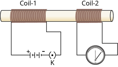
Electromagnetic Induction Between Two Coils
- Coil-1 (Primary): Current-carrying coil (connected to battery).
- Coil-2 (Secondary): Nearby coil connected to a galvanometer.
When current in coil-1 is started or stopped, galvanometer in coil-2 shows deflection.
Why?
Changing current in coil-1 → Changing magnetic field → Induced current in coil-2.
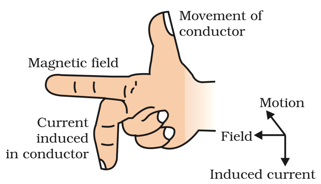
Fleming’s Right-Hand Rule (For Generators)
This rule is used to determine the direction of induced current when a conductor moves in a magnetic field.
Use your Right Hand:
- Forefinger → Magnetic Field (N to S)
- Thumb → Motion of Conductor
- Middle Finger → Induced Current
Electric Generator (Dynamo)
An electric generator is a device that converts mechanical energy into electrical energy using the principle of electromagnetic induction.
- When a coil rotates in a magnetic field, electric current is generated in the coil.
Construction of an AC Generator
| Part | Function |
| Coil (ABCD) | Rotates in magnetic field to induce current |
| Permanent Magnet | Provides the magnetic field |
| Rings (R1 & R2) | Attached to the ends of the coil; rotate with it |
| Brushes (B1 & B2) | Touch the rings and transfer current to the external circuit |
| Axle | Rotates the coil mechanically |
| Galvanometer | Shows the presence and direction of current |
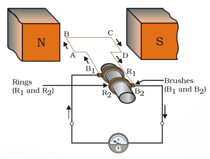
How It Works (Step-by-Step):
- The coil (armature) is rotated mechanically (by water turbines, wind, steam, etc.).
- As the coil spins between magnetic poles, the magnetic field around the coil changes.
- This changing magnetic field induces an electric current in the coil (Faraday’s law).
- The induced current is taken out through the slip rings and brushes.
- The direction of current reverses every half rotation — so we get alternating current (AC).
- In the first half-rotation, current flows from B2 → B1 (direction: ABCD).
- In the next half-rotation, direction reverses: B1 → B2 (direction: DCBA).
Alternating Current (AC)
- Changes direction after equal time intervals.
- In India, AC has a frequency of 50 Hz, i.e., it changes direction every 1/100 second.
How to Get Direct Current (DC)?
- Use a split-ring commutator instead of two full rings.
- This ensures that current always flows in one direction.
This type of generator is called a DC Generator.
| Feature | AC (Alternating Current) | DC (Direct Current) |
| Direction | Reverses periodically | Flows in one direction only |
| Source | AC Generator | DC Generator / Battery |
| Transmission | Easy and less energy loss | Hard and more loss |
| Usage | Homes, industries (AC supply) | Electronics, batteries |
Advantages of AC over DC
- Easier and cheaper to transmit over long distances.
- Can be stepped up or down using transformers.
- Used in almost all power stations.
- AC generator = full rings → current changes direction.
- DC generator = split rings → current flows in one direction.
TRANSFORMER
A transformer is an electrical device that changes the voltage (potential difference) of an alternating current (AC).
- It can increase (step-up) or decrease (step-down) the voltage.
- Transformers work only on AC, not on DC.
A transformer has 3 main parts:
- Core – Made of soft iron. It provides a path for magnetic field.
- Primary Coil – Connected to the AC input.
- Secondary Coil – Connected to the output.
Both coils are wound on the same iron core, but they are electrically separate.
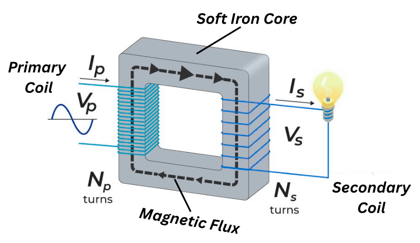
How Does a Transformer Work? (Principle)
It works on the principle of Electromagnetic Induction:
- AC flows through the primary coil, creating a changing magnetic field in the iron core.
- This changing field passes through the secondary coil.
- This induces an AC voltage in the secondary coil.
This process is called mutual induction.
Transformer Formula (Turns Ratio)
Where:
- Vs = Voltage in secondary coil
- Vp = Voltage in primary coil
- Ns = Number of turns in secondary
- Np = Number of turns in primary
Step-Up vs Step-Down Transformers
| Type | Voltage | Current | Turns |
| Step-Up | Increases | Decreases | Ns>Np |
| Step-Down | Decreases | Increases | Ns<Np |
Uses of Transformers
- In power stations to transmit electricity at high voltage (step-up)
- In homes and electronic devices to reduce voltage (step-down)
- In mobile chargers, TV, computer, fridge, etc.
- In voltage stabilizers and adapters
Eddy Currents
Eddy currents are looping currents (like tiny whirlpools of electricity) that are induced in a conductor when it is placed in a changing magnetic field.
They are called eddy currents because they flow in circles (like eddies in water) inside the material.
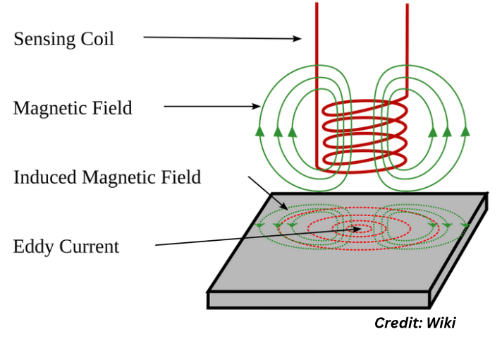
How are Eddy Currents Produced?
Whenever a solid conductor (like a metal plate) is placed in a changing magnetic field:
- The magnetic field induces currents in loops within the body of the conductor (not just on the surface).
- These induced currents are circular, and they oppose the change in magnetic field (as per Lenz’s Law).
Examples in Real Life
- Electric brakes in trains and roller coasters
→ Magnetic fields induce eddy currents in wheels or plates, creating opposing force to slow down the train. - Metal detectors
→ Use eddy currents to detect hidden metal objects.
Disadvantages of Eddy Currents
- They waste energy in the form of heat.
- Cause unwanted heating in transformer cores, electric motors, etc.
How to Reduce Eddy Currents?
- By using laminated cores (thin metal sheets stacked with insulation in between).
This breaks the loops of eddy currents and reduces energy loss.
Domestic Electric Circuits
We receive electric power through the main supply line — either through overhead cables or underground wires. This supply is:
- Alternating Current (AC)
- Voltage = 220 Volts (in India)
Wires in the Circuit: Who Does What?
| Wire Type | Color Code | Function |
| Live Wire | Red or Brown | Carries current into the house (active wire) |
| Neutral Wire | Black or Blue | Returns current back to the supply (completes the circuit) |
| Earth Wire | Green | Safety wire: carries excess/leakage current into the ground |
Earth Wire: Your Safety Net
- Connected to a metal plate buried in the earth.
- Attached to the metal body of appliances like iron, refrigerator, toaster, etc.
- If any current leaks due to faulty wiring or internal defect, the earth wire carries it away safely into the ground.
- Prevents the user from getting an electric shock.
Why Appliances Are Connected in Parallel
- Each appliance gets equal voltage (220 V).
- They can be switched ON/OFF independently.
- If one appliance fails, others still work.
- This is why all home appliances are connected in parallel, not in series.
Electric Fuse
- The fuse is a thin wire made of a metal that melts easily when too much current flows.
Functions:
- Prevents overloading: when many devices are used on a single socket.
- Stops short circuits: when live and neutral wires accidentally touch.
- Breaks the circuit by melting and stopping the flow of dangerous current.
Uses of Electromagnets in Real Life
What Makes Electromagnets Special?
- Their magnetic field is temporary – it appears only when current flows.
- You can control strength by changing current or number of coil turns.
- You can reverse polarity by changing direction of current.
Key Real-Life Applications of Electromagnets
1. MRI Machines (Medical Imaging)
MRI = Magnetic Resonance Imaging
- A strong electromagnet creates a magnetic field.
- The patient is placed inside this field.
- Hydrogen atoms in the body align with the field.
- Radio waves are used to disturb this alignment.
- As atoms return to normal, they emit signals → processed into images.
Electromagnet advantage: Can be switched off after scanning. Safer than permanent magnets.
2. Cranes for Lifting Scrap Metal
- Large electromagnet is attached to a crane.
- When current flows → magnet turns on → attracts metal.
- When current is turned off → metal drops.
3. Electric Bells & Buzzers
- Pressing the switch completes a circuit → current flows through coil → electromagnet forms.
- Magnet attracts a striker → hits the bell.
- Contact breaks → circuit opens → striker goes back → cycle repeats rapidly = buzzing sound.
4. Maglev Trains (Magnetic Levitation)
Use: Superfast trains that levitate above the track using magnets.
How it works:
- Powerful electromagnets lift and propel the train.
- No friction = smoother and faster travel (up to 600 km/h in some cases).
Uses repulsion between magnets to make the train float!
5. Speakers and Headphones
Use: To convert electrical signals into sound.
- Electromagnet attached to a diaphragm (cone).
- When current changes, magnet vibrates → diaphragm moves → air vibrates → sound waves.
